SpinningWing > Helicopters > Helicopter Flight, Control and Stability > Helicopter Autorotation
|
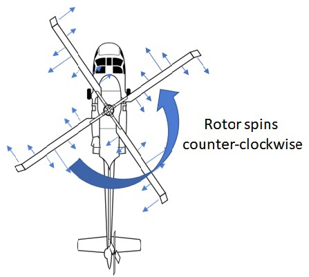
By Jim Davis 2021-04-05 (Last Updated October 4, 2023) Helicopter AutorotationAutorotation is the process of flying a helicopter without applying power to the main rotor. Like an airplane or jet, loss of engine power is not a death sentence. It’s possible to safely land a powerless helicopter using autorotation. (You may want to try our autorotation calculator.) AssumptionsBefore autorotating, it’s assumed that the helicopter is flying high above the ground with significant forward speed. If the helicopter is low to the ground or hovering a much different process will be used. We'll assume the rotor spins counterclockwise when viewed from above. This is the standard for American helicopters. For a clockwise rotor, the yaw and pedal directions discussed herein are reversed. ProcessOverviewUpon losing power, there are four actions a pilot must perform:
Autorotation entry covers the transition from normal, powered flight to steady autorotation. When the helicopter reaches a steady descent rate, forward speed and rotor speed, the entry is finished. The helicopter is now in steady autorotation. At this point, the pilot must identify a landing zone (LZ) and maneuver the helicopter to it. When nearing the LZ, the pilot must arrest most of the forward speed and descent rate to land safely. This is done by flaring, or pitching the aircraft nose up. Each of these phases is described in more detail below. DetectionThe first step is to determine when autorotation is needed. The primary clues are a sharp nose left yaw followed by a decrease in rotor speed. Avionics may also provide a visual or aural alert. This is typically caused by a loss of engine power. Detection must be quick. Rotor speed will drop until autorotation is initiated. Rotor speed substantially below 85% could be lethal. Autorotation EntryAfter detecting the event, the pilot must prevent rotor speed loss. Quickly lowering the collective control helps maintain rotor speed. This is because is reduces aerodynamic torque (drag) that otherwise slows the rotor. Low collective will eventually cause the helicopter to descend. Once at a high descent rate, the upward flow of air through the rotor turns it like a windmill, allowing it to maintain or even gain rotor speed. To further boost the rotor speed, a pilot can pull aft cyclic. This pitches the nose of the helicopter up so that the relative wind (associated with flying forward) blows up through the rotor, providing even more of a windmill effect. This must be limited, however. Aft cyclic also reduces airspeed which is not always desirable. Each helicopter model has an airspeed range that should be used in autorotation. Flying too fast or slow can cause excess descent rate and be deadly. Simultaneous to lowering the collective, the pilot should press right pedal to counter the left yaw. The entry phase is complete when the yaw, pedal, collective, rotor speed, and descent rate are steady. Steady AutorotationOnce the pilot obtains a steady descent rate and airspeed, he must look for a safe LZ. Throughout this phase, he must keep the rotor speed in a safe range, typically between 85% and 105% of nominal speed. The pilot lowers collective to increase rotor speed and raises collective to decrease rotor speed. In this condition, the main rotor is powered by the upward airflow associated with the helicopter’s descent—the upward flow of air keeps the rotor spinning like a windmill. The tail rotor is geared to the main rotor and hence maintains a rotational speed proportional to the main rotor speed. In this flight condition, a pilot must also monitor airspeed. Two important airspeeds are (1) the airspeed that minimizes descent rate and (2) a larger airspeed that provides maximum glide distance. The airspeed that minimizes descent rate is approximately the airspeed that requires minimum power (max loiter time) in level flight. This is typically around 60 knots and results in a descent rate around 2000 feet per minute. The airspeed that provides maximum glide distance is approximately the optimal cruise speed. This is often around 90 knots, where the ratio of forward speed to power is largest. Just as in powered flight, turns may be required to reach the LZ. These are executed in much the same way as powered flight, but with the added complication of maintaining rotor speed. The rotor tends to speed up when a helicopter turns in autorotation, so the pilot must pay particular attention. We describe the physics of these turns in a separate section below. Flare LandingApproaching the LZ the helicopter must reduce its forward speed and descent rate quickly. Flaring, or pitching the nose up, does both simultaneously. When the aircraft pitches up, more air flows up through the rotor than in descent. This increases rotor thrust, delivering both a vertical and aft force. As the vertical and forward speeds approach safe values the pitch is removed with forward cyclic. This enables the helicopter to land flat on the ground. As the cyclic is moved forward the collective is increased to keep the descent rate small and soften the landing. At this point the rotor speed drops. Timing is critical here. If the flare is executed too high above the ground, the helicopter will drop a longer distance after the flare and accelerate down. This will result in a harder ground impact with a lower rotor speed. If the flare is done too late the helicopter will contact the ground before the descent rate and/or forward speed is sufficiently arrested, also resulting in a hard landing. While most of the forward speed is removed in the flare, it's not always necessary to remove it all. With a suitable LZ, the helicopter can land with some forward speed and slide or roll to a stop. This makes the landing slightly easier for the pilot. However, in some cases the terrain may not allow for a sliding landing. In such cases, pilots must reach zero ground speed just before touching down, called a "zero-zero autorotation" (0 speed at 0 altitude above ground). This is more difficult and typically results in a harder ground impact. Physics of the Windmill EffectThe acceleration of the rotor is proportional to the net torque acting on the rotor. Normally the engine supplies (positive) torque to counter (negative) torque from rotor aerodynamic forces. The result is zero net torque and constant rotor speed. Without engine power, aerodynamic forces alone must result in zero net torque. We’ll see that the air flowing up through the main rotor (due to the aircraft descent), along with the aerodynamic shape of the blades, facilitates this. The main rotor is geared to the tail rotor and effectively powers the tail rotor in autorotation.
If we zoom in on sections of a rotor blade, each by itself generally provides nonzero torque. For example, the innermost and outermost portions of a blade typically would slow the rotor in autorotation. We'll call this negative torque. However, a portion of a blade between these two regions provides positive torque. In total, the torque sums to zero, facilitating constant rotor speed. The direction of torque contribution is shown with arrows in the picture above. Below we’ll investigate the aerodynamics of cross sections of a blade in detail. Specifically, you'll see how a section can provide positive torque like a windmill.
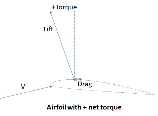
A cross section of a blade is shaped like an airfoil shown in the diagram above. A key property of these airfoil shapes is high lift relative to drag. Lift is the aerodynamic force acting perpendicular to the relative air velocity \(V\), while drag is parallel. Since the aircraft is descending at a high rate and the rotor is spinning, the relative air velocity to the blade is at an angle shown in the diagram above. It's mostly right, but with an upward component due to aircraft descent. Since lift is perpendicular to \(V\), it's tilted slightly left, into the direction of rotor rotation. The drag mostly acts against rotor rotation. Since the lift is so much larger than the drag, the forward component of the lift (the dotted horizontal blue line at the top) has the potential to more than offset the aft portion of the drag. This results in positive torque that allows the rotors to maintain speed without engine power.
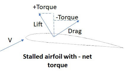
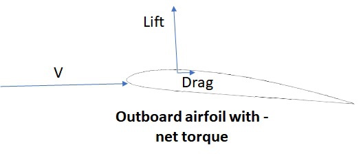
You may wonder why the inboard and outboard sections of the blade do not contribute positive torque. The speed of a blade section due to rotor rotation is proportional to the distance from the center of the rotor. This is very small for inboard sections and very large for outboard sections. This results in a large angle of incidence \(\alpha\) inboard and much smaller \(\alpha\) outboard. Above a threshold \(\alpha\), drag increases significantly and lift decreases. This is called stall, and in this context stall prevents inboard sections from producing positive torque. This is shown in the diagram above.
The small \(\alpha\) outboard prevents positive torque in three ways. First, it shrinks the lift-to-drag ratio relative to the "positive torque blade sections." At small incidence angles drag decreases slightly, but lift decreases dramatically. Next, the lift force (perpendicular to \(V\)) is directed more upward. So the lift is both smaller and directed less favorably. Finally, the drag is also directed less favorably. Drag is parallel to \(V\) and hence more aft. This is all summarized by the picture immediately above. Together, this results in a negative torque contribution outboard. Maneuvering in AutorotationHow do things change in a turn / maneuvering? When the helicopter turns it rolls to a blank angle, say, \(\phi = 35deg\). At the same descent rate, the up flow through the rotor drops about 20% (from \(w\) to \(w\cos 35^o \)). Thrust and rotor speed cannot be maintained in this condition. The helicopter accelerates toward the ground, increasing flow up through the main rotor. This persists until vertical aerodynamic forces, primarily from the main rotor, can support the helicopter’s weight. At this point, main rotor thrust will be significantly larger than in level autorotation. In addition to countering the helicopter's weight, there is a large amount of thrust parallel to the ground, in the direction of the turn. This counters the centrifugal force that would otherwise push the helicopter out of the turn. To reach this condition, the flow through the main rotor must be significantly larger than in level flight autorotation. This means the rotor speed will increase in a turn. Collective is increased to counter this and maintain safe rotor speed. |